Buffer connection on one side
A simple way to improve stratification in the buffer

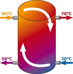
Two-sided buffer connection
It is very common to see in hydraulic plans and installations that heat generators and heat consumers are connected to buffer tanks in separate connections for each height (top, bottom, possibly also centrally). However, this often has a negative effect on the flow and thus on the stratification of the buffer tank, as the following example illustrates. Let's assume that a 28kW log boiler (90°C flow temperature) loads a buffer storage tank, while at the same time a radiator circuit (70/50°C) and a floor circuit (40/30°C) are supplied with a total of 14kW. Let us further assume that the two heating circuits are connected to the buffer by rendeMIX return utilisation with 70/30°C in total. When the buffer is connected on both sides, the entire boiler volume flow flows into the buffer at the top left and is removed again at the bottom left. In addition, the entire system volume flow is taken out at the top right and fed back in at the bottom right. The following formula therefore applies:
Buffer water flow rate = boiler volume flow rate + system volume flow rate
This very easily leads to a mixing of different temperatures in the buffer, which results in the system flow (70°C) being colder than the boiler flow (90°C) and the boiler return (50°C) being warmer than the system return (30°C). This in turn increases the volume flows, because
Boiler volume flow = 6/7 × boiler output : boiler delta-T = 6/7 × 28kW : (90-50)K = 0.6m³/h
System volume flow = 6/7 × system output : system delta-T = 6/7 × 14kW : (70-30)K = 0.3m³/h
Water flow rate of the buffer = 0.6m³/h + 0.3m³/h = 0.9m³/h

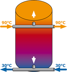
Buffer connection on one side
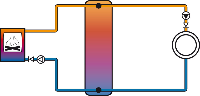
If, on the other hand, the buffer is connected to the connecting pipe between the heat generator and the heat consumer with only one connection per buffer height, only the difference of both volume flows through the buffer instead of the sum:
Buffer water flow rate = Boiler volume flow rate - System volume flow rate
The associated lower water flow rate of the buffer improves the stratification, so that the system flow (90°C) now has the same temperature as the boiler flow (90°C) and the boiler return (30°C) has the same temperature as the system return (30°C). This in turn naturally reduces the volume flows, because
Boiler volume flow = 6/7 × boiler output : boiler delta-T = 6/7 × 28kW : (90-30)K = 0.4m³/h
System volume flow = 6/7 × system output : system delta-T = 6/7 × 14kW : (90-30)K = 0.2m³/h
Water flow rate of the buffer = 0.4m³/h - 0.2m³/h = 0.2m³/h
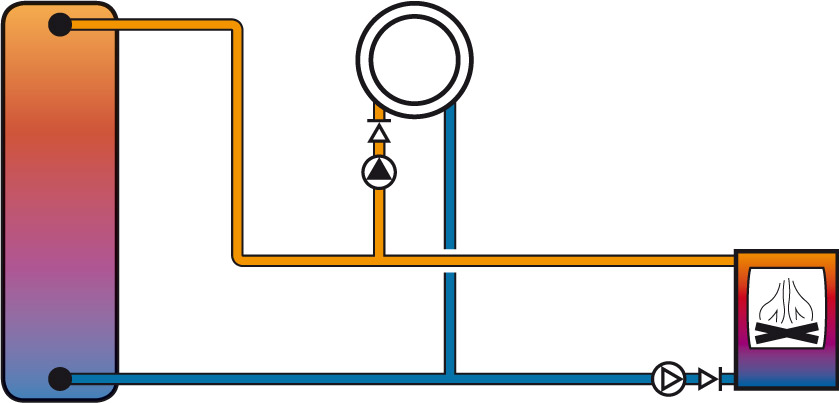
Due to the one-sided connection of the buffer, the water flow rate of the buffer was increased by 78% reduced. We indicate this one-sided connection of the buffer in our hydraulic diagrams by black dots in the buffer.

It is not necessary to place the buffer between the heat generator and the heat consumer. It can just as well be mounted on a branch line that runs from the connection line between the heat generator and the heat consumer.

This often means greater design freedom in the installation with reduced pipe length. In order to ensure the hydraulic decoupling associated with the installation of a buffer storage tank, however, the cross-sections of these pipes must be sufficiently dimensioned. This applies in particular when using differential pressure-controlled circulating pumps.

