
Automatic and dynamic hydraulic balancing
 In circulating water heating systems, we use water as a storage and transport container for heat. But how much water is actually needed and how do you ensure the "right" amount of water in relation to the amount of heat transported, transferred or stored? In this article, we want to show that a thermostatic approach can solve this problem more easily (automatically) and better (dynamically).
What are the benefits of hydraulic balancing? The purpose of hydraulic balancing is to provide each consumer in a distribution network with the "right" amount of water. This must not be too small, because otherwise the consumer is not sufficiently supplied with heat; but it must also not be too large, because otherwise the workload of the circulating pumps increases disproportionately and the supply of other consumers is possibly impaired. In addition, hydraulic balancing has the further task of increasing the thermal network efficiency, because low return temperatures are one of the prerequisites for low-temperature sources, such as latent condensing heat, solar heat or other regenerative heat sources, to actually be used by the consumers. In addition, practical experience shows that systems with excessively high return temperatures or excessively high circulating water volumes have significantly lower consumption (in some cases up to 40%) after hydraulic retrofits, even without regenerative sources.
The same task exists in principle for the hydraulic integration of heat generators: If the quantity of water flowing through them is too large, the flow temperature will not reach the desired setpoint with the same negative consequences, especially when loading buffer storage tanks. The "right" amount of water is therefore always as small as possiblebut of course always as large as necessary. But now the question arises: how do you find these "right" amount of water and how do you set them in a technically reliable way?
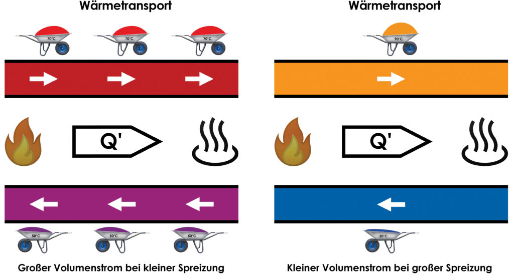
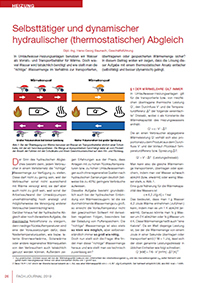
Fig. 1: When transferring heat, we use water as a transport container similar to a wheelbarrow with which we transport sand. The amount of sand transported depends on the product of the number of trips with the wheelbarrow and its weight difference on the way there and back.
§ 1 of the theory of heat always applies
In circulating water heating systems, the following simplified rule of three applies to the thermal power Qꞌ transported or transferred from heating surfaces, the flow Vꞌ and the temperature difference ΔT, where c contains the heat capacity of the heating water as a constant:
Qꞌ = c - Vꞌ - ΔT
The heat output Qꞌ delivered to a consumer is therefore proportional to the product of the flow Vꞌ and the flow/return temperature difference or spread ΔT:
Qꞌ ~ Vꞌ - ΔT (power rate)
One can therefore transport, transfer or store the same amount of heat by cooling (or heating) a lot of water weakly or by heating a little water strongly, see Fig. 1. A good approximation for the heat capacity of water is
c ≈ 4.2 J/(g-K) = 1 cal
This means that you can extract (add) 4.2 joules of heat from 1 gram [g] of water by cooling (heating) it by 1 Kelvin [K]. In the same way, you could cool ½ g of water by 2 K or ¼ g of water by 4 K. This amount of heat is also called "a calorie". Since one watt is the power at which the amount of heat of one joule is transferred or transported in one second (1 W = 1 J/s), the above power rate can be written in common units as follows:
Qꞌ [kW] = 7/6 - Vꞌ [m³/h] - ΔT [K]2
For example, a consumer with a nominal power of QꞌN = 28 kW, which is required for a nominal spread of ∆TN = 20 K (e.g. 80/60°C or 50/30°C), a nominal volume flow of:
VꞌN = 7/6 - 28 kW / 20 K = 1.2 m³/h
Nothing new so far.
Non-automatic and static hydraulic balancing ...
... is to adjust the flow through this consumer to this nominal volume flow after having calculated it beforehand. By "non-automatic" we therefore mean that the hydraulic balancing cannot be carried out without knowledge of all the individual nominal volume flows, which is a hurdle that should not be underestimated in the case of renovation alone. But what happens if the consumer that has been "correctly" adjusted in this way consumes less than the nominal output at partial load? For example,
- because it is an air heater whose fan has been switched off by an electric room thermostat?
- because it is a drinking water storage tank that only has to cover the standby losses of the hot water circulation?
If there is no adjustment of the water flow Vꞌ to the reduced power output Qꞌ, then, because Qꞌ ~ Vꞌ - ∆T always applies, there must be a reduction in the temperature difference ∆T! By "static" we thus understand that with partial load there is no adjustment of the flows Vꞌ to the actually transferred thermal power Qꞌ.
Speaking of partial load
At this point, we would like to make a clear distinction between two very different types of "partial load":
Weather-controlled partial load
With weather-compensated partial load, we assume that due to the thermal conduction of the building envelope, the heating load basically increases proportionally with the difference between the outdoor temperature and the room temperature. The flow temperature is then raised via the heating curve when the outdoor temperature drops. The slope of the heating curve indicates by how many Kelvin the flow temperature is raised when the outside temperature drops by one Kelvin. The partial load is thus controlled via the flow temperature with almost constant water circulation. Since the transmission power of the heating surfaces is approximately proportional to the difference between their mean temperature and the room temperature, the return temperature follows a second, flatter heating curve that intersects the first heating curve at the heating load of zero. At this point, the spread is then also zero. The heating load Qꞌ is thus proportional to the spread ∆T, while the water circulation Vꞌ remains almost constant over the entire weather-controlled load range:
Qꞌ ~ ∆T | Vꞌ = const. (Delta-T control via the supply temperature), see Fig. 2.

Fig. 2: With weather-compensated partial load, the flow temperature is lowered with the load, while the flow rate remains almost constant. Since the average heating surface temperature thus also decreases, the return temperature also follows a heating curve, albeit a flatter one.
Media-guided partial load
In the case of a medium-controlled partial load, we assume that in any weather-controlled load case - i.e. with an arbitrary, but fixed assumed outdoor temperature and a sufficiently dimensioned, but also constant flow temperature derived from this via the correct heating curve - there is a setpoint/actual deviation of the temperature of the target medium, e.g. the room temperature. Ideally, the target temperature controllers then throttle the flow through the heating surfaces:
Qꞌ ~ Vꞌ |∆T = const. (flow control)
For example, the thermostatic valves of the radiators in the two-pipe systems operate if the bypasses in the tap blocks are closed. In the media-controlled partial load case with flow control, the flow through the heating surfaces therefore decreases and the spread remains at least constant. In the case of thermostatic valves, the return temperature even decreases because the average heating surface temperature decreases with the heating load. The network is hydraulically relieved and its thermal efficiency increases, see Fig. 3.
Unfortunately there is also the other case: The heat loss is reduced at a constant flow rate:
Qꞌ ~ ∆T | Vꞌ = const. (Delta-T control via the return temperature)
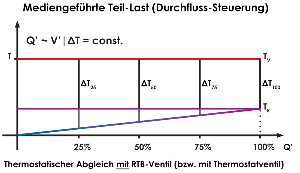
Fig. 3: If, for example, the thermostatic valves throttle the flow through the radiators of a two-pipe network when the room temperature is excessive, the spread even increases because the average heating surface temperature drops with the transmitted power, which also causes the return temperature to drop. The network is thus relieved hydraulically (water circulation) and thermally (return temperature).
This happens, for example, when the fan of an air heating coil is switched off by the electric room thermostat or in single-pipe radiator trains: Now the spread ∆T must decrease with the thermal output Qꞌ, which means that at a constant flow temperature, the return temperature increases. The network is not hydraulically relieved; its thermal efficiency decreases, see Fig. 4.
Fig. 4: If, on the other hand, the power transmission is reduced without lowering the flow rate, as happens, for example, with air heating coils or in single-pipe heating lines, the return temperature rises because only the spread decreases with the transmitted power. The network is therefore not relieved hydraulically (water circulation) and its thermal efficiency decreases (return temperature increases).
How does this affect the individual heating surfaces?
Almost all heating surfaces have separate individual controllers to regulate the temperature of their target media:
- RLT system: Three-way mixer opens/closes continuouslyIII, unfortunately mostly decoupled by a switch in front of itI
- Air heating coil: Room thermostat switches fan on/offI
- Radiant ceiling panels: Room thermostat opens/closes zone valve completelyII
- Radiator/2-pipe system: Thermostatic valve throttles flow continuouslyIII
- Radiator/1-pipe system: All bypasses remain openI
- Underfloor heating: Thermostatic valve opens/closes completelyII
- Drinking water storage tank: Charging pump switches on/offII
- Swimming pool water: Zone valve opens/closes completelyII
The following three cases can be distinguished:
(I) The flow remains constant over the entire partial load range (No flow control at all).
(II) The flow remains constant above the partial load of zero (two-point flow control on/off).
(III) The flow is controlled over the entire range of the partial load (Steady flow control 0-100%). Obviously, case I represents the worst, case II the second worst, and only case III the best solution for the desired goal of making the supply security and the hydraulic and thermal network efficiency as high as possible.
Two-point control and thermal efficiency
Since the essence of two-point control is to switch the heat transfer on and off completely, the heat transfer can only be reduced by limiting the transfer time. This means
- During the Shutdown phases the heating surfaces do not contribute to the return temperature, as there is no flow.
- During the Switch-on phases the heat transfer must take place to a more limited extent in terms of time and thus with a higher specific surface power (power per unit area of the heating surface or heat exchanger), which results in an increased surface temperature and thus an increased flow rate and an increased return temperature.
Two-point control is therefore inferior to proportional or continuous control not only for reasons of thermal comfort (occasionally cold floor surfaces are not infrequently criticised in new buildings), but also because of the more efficient use of scarce heating surfaces.
Automatic and dynamic hydraulic balancing
If a thermostatic heater is now installed in the return of a heating surface, the Return temperature limiter (RTB) which, as an automatic control valve, throttles the flow as a function of the return temperature, the return temperature increase associated with the two worst cases I and II causes the flow through the heating surface to be reduced and thus compensates for the return temperature increase. This occurs both at full load in the nominal state "automatically" - i.e. without knowledge of the nominal volumetric flow - and at medium-controlled partial load "dynamically" - i.e. depending on the temperature of the target medium. In this way, the two undesirable cases I and II mentioned above are converted into the desirable case III without having to undergo the procedure of calculating all individual flow rates, which is often not even possible in the case of renovation and is quite an athletic task even in the case of complete pipe network calculation in new buildings, if one occasionally takes a look at the computer-calculated numerical carpets that are handed over to the fitters for this purpose.
The same applies in particular to peak load boilers
If, for example, a peak load boiler is to maintain the top zone of a buffer storage tank at a minimum temperature without immediately charging the entire buffer, which is reserved for the generally weaker regenerative heat generators, it must of course charge the buffer with at least this temperature (plus an allowance for transport losses and hysteresis). But how can this be ensured if, in particular
- the return temperature and
- the modulation power
of the peak load boiler? The only solution then is a measurement of the boiler flow temperature and a regulation of the boiler volume flow derived from this. We have called these valves, which unlike those of the heat consumers must open when the temperature rises, flow temperature limiters (VTB).
What about the quality of the rules?
We have found that it is advantageous to equip these return temperature limiters (RTB), as well as the supply temperature limiters (VTB), with a minimum circulation (MUL) in the order of one percent of their nominal flow, so that the flow can never become zero. Otherwise, in the event of an overshoot after a sharp drop in load - e.g. when the fan motor of an air heater is switched off as mentioned above - there would be a risk that the return temperature sensor would be disconnected from the actual heat consumption of the heating surface due to water standstill, so that the return temperature limiter (RTB) would not open or would only open too late if there were a renewed load demand in the meantime. Especially for fan-operated heating surfaces, the associated warm start is not only a comfort requirement, but also an operational safety requirement in the case of outside air supply in the event of frost.
Of course, the control quality - as always - depends essentially on the quality of the temperature measurement. Therefore the Sensors close to the outputs of the heating surfaces (lowest possible dead time!) and - especially in the case of self-operated controllers - as an immersion sensor. Completely surrounded by heating water Therefore, appropriate work preparation is indispensable. Furthermore, each individual parallel line of a network must be calibrated in the same way, i.e. each RLT system, each air heating coil, each radiator single-pipe line, each surface heating loop, each drinking water storage tank and each swimming pool water heat exchanger.
How does this look in connection with the heating curve?
The use of the return temperature limiter (RTB) leads to a flattening of the heating curve of the return temperature and thus also of the heating surface mean temperature over the control range of the weather-compensated partial load compared to the design case. This must be compensated for by a corresponding increase in the flow temperature or steepness of the heating curve. Below are some examples, see Fig. 5.
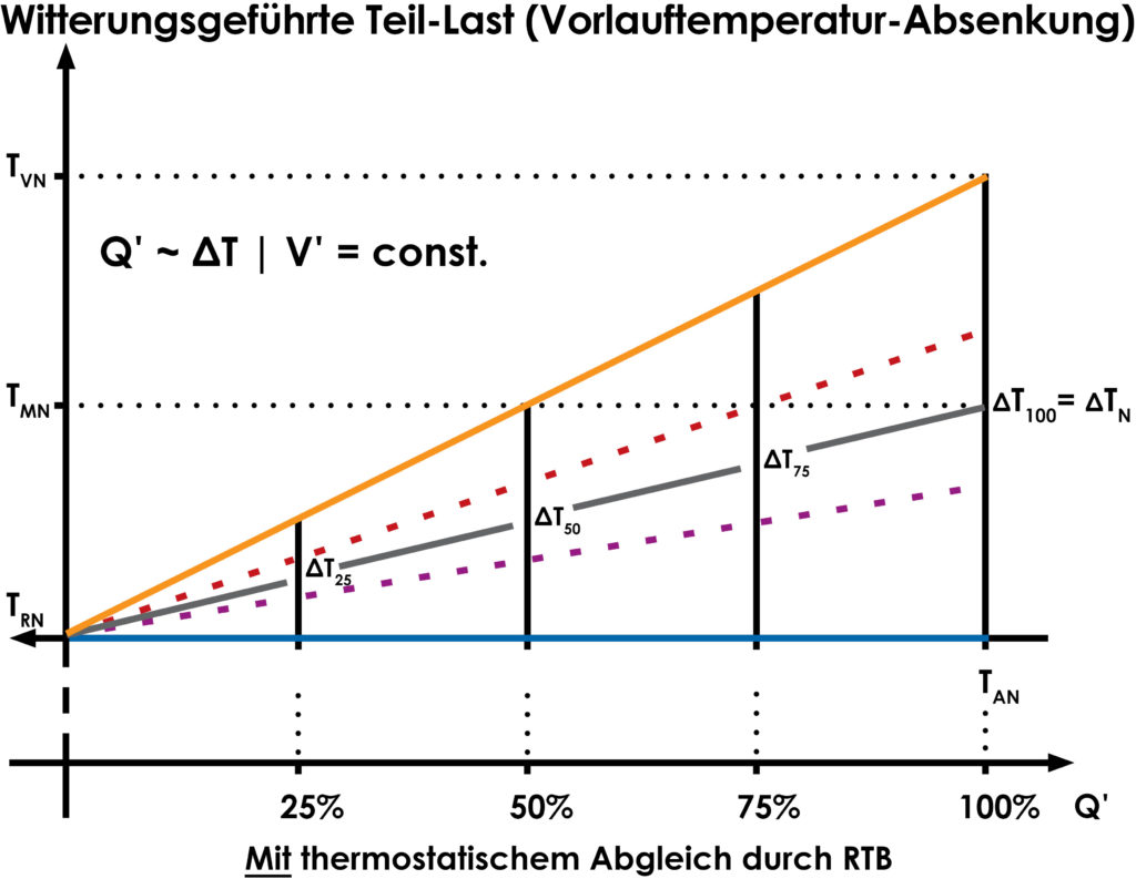
Fig. 5: If heating surfaces with return temperature limiters (RTB) are operated on weather-compensated heating curves, the return temperature is constant. However, the heating surface output can only be maintained at the same average heating surface temperature, which is why the flow temperature must be raised. Due to the higher spreads, the output is then transferred at significantly lower flow rates and significantly lower return temperatures, so the network operation is hydraulically relieved and thermally more efficient. The condition that the flows are almost constant over the entire weather-compensated load range is maintained, which can be seen from the fact that the spread rises and falls proportionally to the weather-compensated load.
What is the significance of this for the self-regulating effect?
For the underfloor heating systems marked with * in Tab. 1, the return temperature controlled by the RTB is practically the room temperature. As a result, the so-called self-regulating effect of the underfloor heating is increased. The term "self-regulating effect" refers to the fact that with underfloor heating the average heating surface temperature is only a few Kelvin above the room temperature. For example, in a new building (design: 35/28 °C) at 50 %iger weather-compensated partial load (28/24 °C), this is 26 °C and thus 6 K more than the room temperature of 20 °C. If the room temperature now rises by 1 K to 21 °C, this temperature difference drops by 1 K to 5 K, i.e. by 1/6 or 17 %. However, this temperature difference is approximately proportional to the heat output delivered by the heating surface, so that the increase in room temperature is compensated for by a reduced heat supply.
As already explained, however, a heating surface reacts with a constant flow and reduced heat output with an increase in the return temperature and thus with an increase in the average heating surface temperature. The self-regulating effect is therefore partially cannibalised in static hydraulic balancing without RTB. In the case of dynamic balancing with RTB, on the other hand, these cancel out the increase in return temperature due to the reduction in flow rate, whereby the self-regulating effect only takes full effect, see Fig. 6.
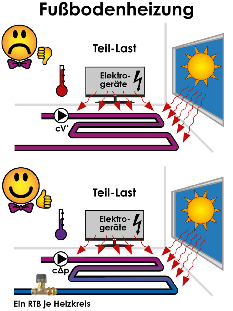
Fig. 6: With surface and underfloor heating systems, the return temperature can be so close to the room temperature that the self-regulating effect is supported and an "automatically acting device for room-by-room control of the room temperature" in the sense of the EnEV can be realised by means of the return temperature limiter (RTB), which, however, has no remote control and no switch-off function. However, as continuous controllers, the return temperature limiters (RTB) are superior to two-point controllers in terms of comfort and efficiency.
What exactly does the EnEV require?
According to § 14 (2) EnEV, "heating systems with water as the heat transfer medium ... must be equipped with automatic devices for room-by-room control of the room temperature when installed in buildings". It is therefore not written that the setpoint value must be entered in the room. Since most individual room controllers for underfloor heating are equipped with two-point controllers, the control of the room temperature via continuously acting RTB is superior to them from the point of view of thermal efficiency - as described above. Only if the room is used as a living room and bedroom would the switch-off function of the usual individual room controllers be additionally advantageous.
And what do BAFA + KfW have to say about it?
Under point 5.25 "Opening clause for innovative technologies" of the "Annex to the leaflets" of KfW for "Energy-efficient refurbishment - Loan (151/152)", "Energy-efficient refurbishment Investment grant (430)" and "Energy-efficient construction (153)" it is written: "If system components are used in residential buildings for whose energy assessment there are no recognised rules of technology or verified empirical values published in accordance with EnEV Section 9(2), second sentence, third half-sentence, components with equivalent or worse energy properties may be used for this purpose." The term "components can be used for this purpose" refers to the conventional methods and components of non-automatic and static hydraulic balancing illustrated in the EnEV calculation standards.
The innovative technology must therefore be equivalent or better, which the thermostatic return temperature limitation, as an automatic and dynamic, hydraulic balancing of the heating circuits, may claim for itself. For this reason, the installation and correct setting of the RTB (VTB) is subsidised by both BAFA and KfW.
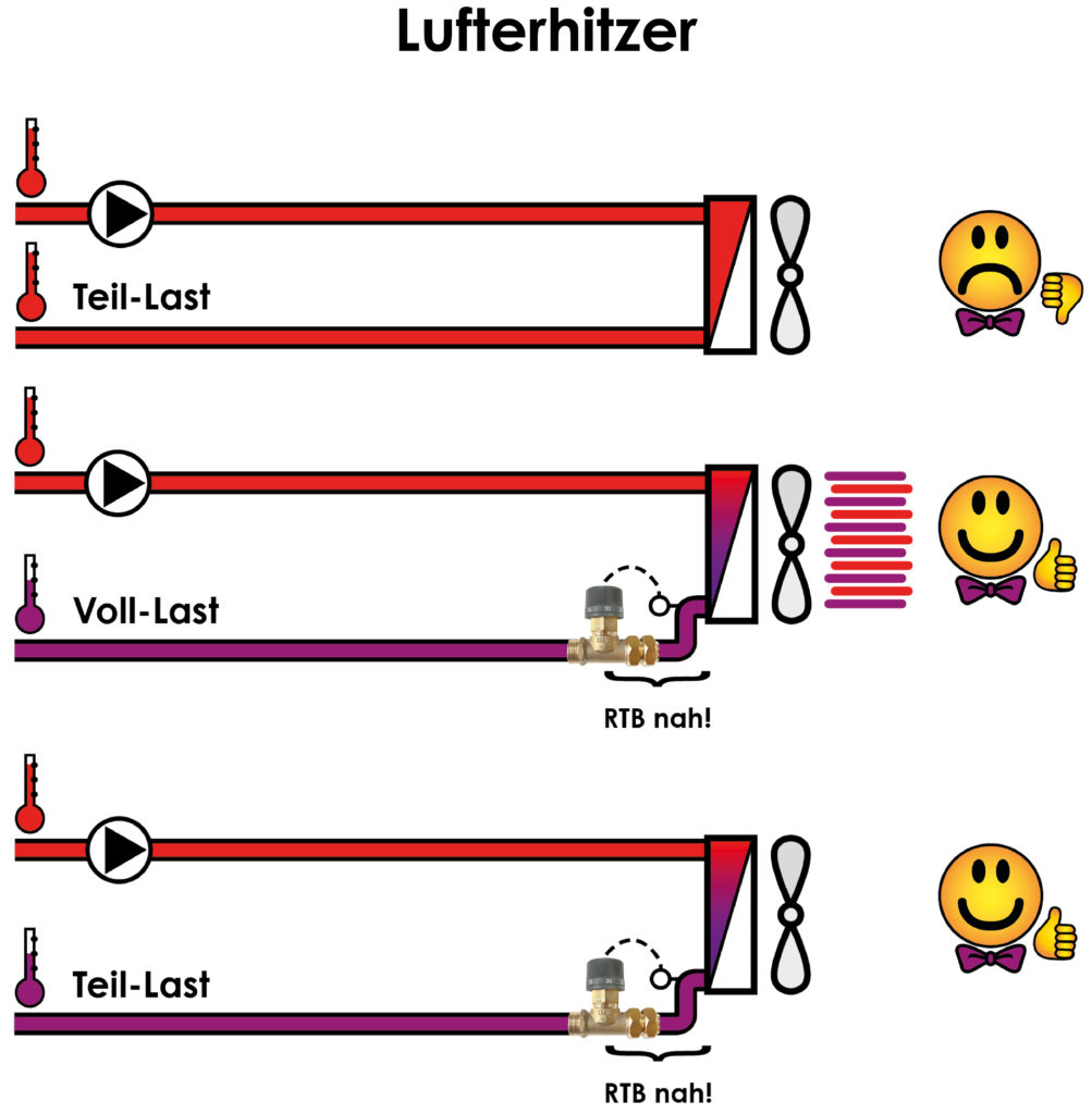
Fig. 8: By installing return temperature limiters (RTL), the flow rate of air heating coils is automatically adjusted both at full load (full fan speed) and at partial load (reduced fan speed) and when the fan is switched off. The thermostatic control function with fixed minimum circulation guarantees a warm start and frost protection.
A final remark on balancing energy
Control energy is the mechanical work required to open or close the control valve. In large systems, it is often applied by means of electrical auxiliary energy, i.e. via electrical drives. Especially in small systems, a large number of control valves without auxiliary energy are used for hydraulic balancing. However, this only means that they do not require an additional energy supply, but not that they do not need any energy to function. But where do they get the energy they need to function?
Hydraulically driven valves
The line regulating valves used are designed to keep either a differential pressure or a flow rate constant. Usually, the mechanical stroke of the valve actuator is generated via a diaphragm from the differential pressure of the hydraulic network itself. In order for the regulator to work at all, a minimum pressure drop - usually around 2 mWS - must therefore be ensured, which means additional work for the circulating pumps.
Thermally driven valves
With thermally driven valves, on the other hand, this work arises from the expansion or evaporation of a medium with which the temperature sensor is filled. Because the control energy is thus extracted from the heating water in the form of heat, the quality of the thermal connection of the sensor plays the special role already described above. But once this task has been solved during installation, such valves do not require any additional minimum pressure drop for the rest of their service life and consequently no additional work by the circulation pumps, not to mention the issue of "flow noise". It can thus be concluded that a thermostatically balanced network can be operated with significantly lower differential pressures and thus significantly lower hydraulic workload for circulating pumps than a hydraulically line-regulated network.
Summary
The installation of thermostatic return temperature limiters
- Enables automatic hydraulic balancing, i.e. without knowledge of the individual nominal volume flows.
- Increases thermal network efficiency through dynamic adaptation to the media-controlled partial load
- Relieves the network of additional pump work for operating differential pressure-driven line regulating valves
- can be used with underfloor heating as individual room control - but without switch-off function
- is recognised and promoted by BAFA and KfW as at least equivalent, and
- has already been tried and tested thousands of times.
Download the technical article as PDF
