
Thermostatic balancing with RTB valves
The purpose of hydraulic balancing
 is to provide the right amount of water to each consumer in a distribution network. This must not be too small, because otherwise the consumer will not be sufficiently supplied with heat. But it must also not be too large, because otherwise its return temperature will rise too much, the supply to other consumers will be impaired and the network efficiency will drop. But what is the "right" amount of water?
Basically
in circulating water heating systems for the thermal power Q' delivered by a heat exchanger, the flow V' and the temperature difference ΔT the following rule of three, where c contains the heat capacity of the water as a constant:
Q' = c - V' - ΔT
The heat output delivered to a consumer is therefore proportional to the product of the flow rate and the temperature difference.
Q' ~ V' - ΔT
So you can deliver the same power by cooling a large amount of water a little bit or a small amount of water correspondingly more.
A good approximation for the heat capacity of water is
c = 4.2 J/(g-K) = 1 cal
This means that you can extract 4.2 joules of heat by cooling 1 g of water by 1 K. Similarly, you could cool ½ g of water by 2 K or ¼ g of water by 4 K. This amount of heat used to be called a calorie.
1 W = 1 J/s
Since one watt is the power at which the amount of heat of one joule per second is transported, the above power rate can be written in common units as follows:
Q' [kW] = 7/6 - V' [m³/h] - ΔT [K]
This means, for example:
a consumer with a nominal power of 28 kW, designed for a nominal temperature difference of 20 K, has a nominal volume flow of 1.2 m³/h:
V' [m³/h] = 6/7 - 28 kW / 20 K = 1.2 m³/h
These ratings must always be taken from the performance data on the type plate or from the data sheet!
The hydraulic balancing
is now to limit the flow through this consumer to this nominal value, for which flow rate and differential pressure control valves are used.
But what if the consumer draws less than rated power? For example:
- because it is an air heater whose fan is switched off by an electric room thermostat?
- because it is a drinking water storage tank that only has to cover the standby losses of the circulation?
If there is no adjustment of the water quantity V' to the reduced power output Q', then, because Q' ~ V' - ΔT, there must be a reduction in the temperature difference ΔT! However, a reduction in the temperature difference can only mean an increase in the return temperature, because the flow temperature in the network remains constant.
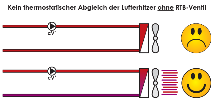
No Thermostatic balancing of the air heaters without RTB valve
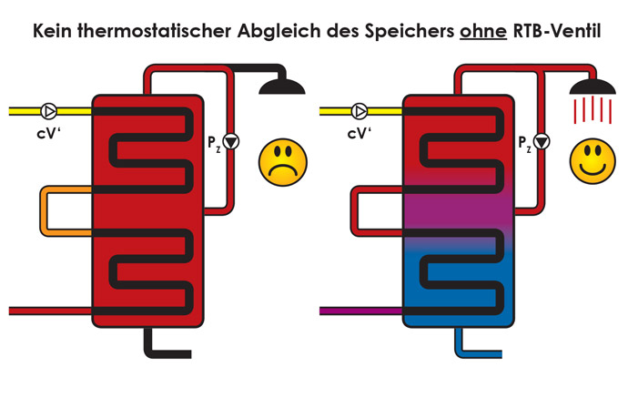
No thermostatic balancing of the storage tank without RTB valve
Because without the installation of RTB valves (return temperature limiters), the volume flow is constant (cV') even when the hydraulic balancing has been carried out properly, the return temperature can only assume the lowest value when the fans of all air heaters are running at the same time or the drinking water storage tank is heating up fresh cold water. Since this is not the case all the time, a condensing boiler system, for example, can never run in condensing mode all the time, or a solar system can never fully exploit its yield potential.
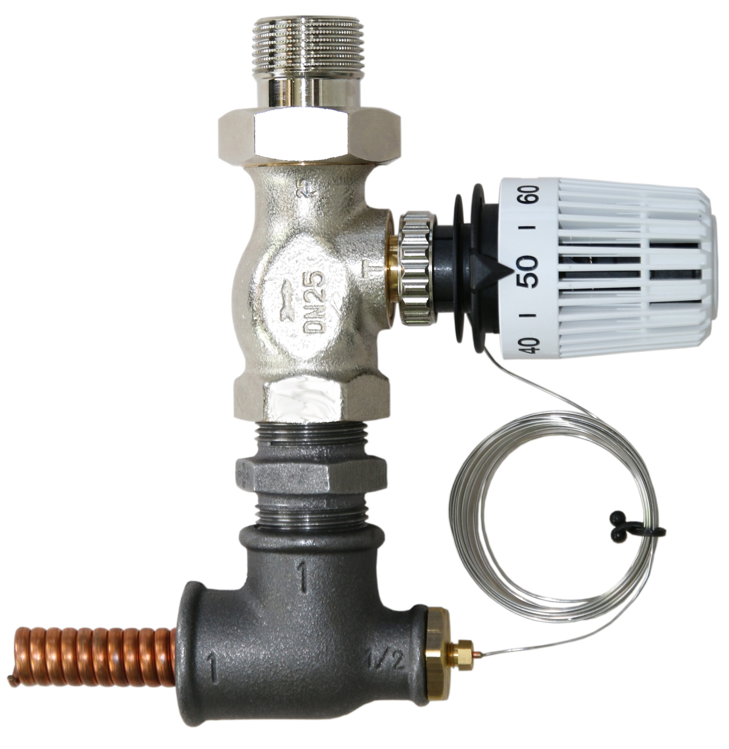
Thermostatic balancing is
a very simple method to solve this problem and consists of installing a return temperature limiter (RTB) in each individual parallel consumer line. This thermostatic valve limits the return temperature to the set maximum value. If this is undershot, the valve is fully open; if it is exceeded, however, the valve is closed down to a minimum flow of approx. 1% of the nominal value. The sensor must be installed as close as possible to the outlet of the consumer in order to keep the reaction time as short as possible, which is especially important for air heaters. The minimum flow rate not only shortens the reaction time, but also ensures an immediate warm start and guarantees frost protection.

Thermostatic balancing of the air heaters with RTB valve
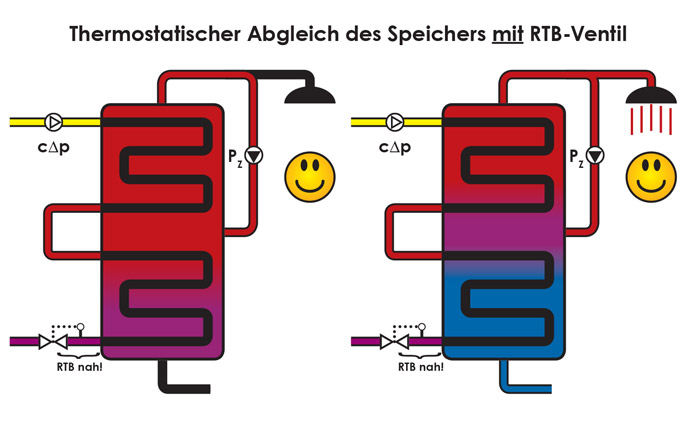
Thermostatic Adjustment of the memory with RTB valve
A pleasant side effect
of this measure, which is as simple as it is efficient, is that you can save yourself the installation of volume flow and differential pressure control valves in the future: You simply set all consumers such as air heaters or drinking water tanks in the pipe network to a certain temperature difference, determine the corresponding flow temperature and set all RTB valves to the corresponding return temperature.
For example: Air heater
Assume that the air heaters are all set to 70/50°C at nominal output. Then select the heating curve slope accordingly and set the RTB valves to 50°C. If it is too cold in severe cold, then increase the steepness of the heating curve; if the return temperature rises too much in mild cold, then lower the maximum values of the return temperatures at the RTB valves. Lower the maximum values of the return temperatures as much as possible. A practical value has proven to be 40 to 45°C at 75 to 80°C flow temperature in the design case (nominal load). The speed of the fans should be set to the lowest possible value, which increases the outlet temperature of the air and reduces draughts and noise. The return temperature can never fall below the temperature of the air drawn in by the air heaters.
For example: Drinking water reservoir
The most important thing when charging the storage tank is that the storage tank is charged through in one go without interrupting the burner. For this purpose, the boiler flow temperature must be set as high as possible in charging mode. Now the return temperature can be limited to a value just below the circulation return temperature. Practical values for small systems (according to TrinkwV) have proven to be 45 to 55°C. For large systems (according to TrinkwV), at least 55°C should be selected and 70°C for thermal disinfection. In all cases mentioned, the flow temperature should be at least 85°C in charging mode. These specifications correspond to the conclusion of the Statement by the Federal Environment Agency "Saving energy in water heating - Compatibility of energy saving and hygiene requirements for drinking water" from September 2011. Incidentally, we would also like to draw attention at this point to the connection between Drinking water hygiene and tank surface quality refer.
The circulating pump
is dimensioned as before to the total water quantity of all consumers at nominal capacity and set to the smallest possible setpoint in the operating mode "Differential pressure constant (cΔp)". In this case, values of over
Δp = 250mbar = 2.5mWS
recommended. Such exceptions are, for example, decentralised fresh water modules in home stations without their own pump with proportional valves without auxiliary energy.
Example of the successful refurbishment of a manufacturing plant
Product links: