Two-zone principle
Advantages at a glance
- Up to 100% more yield with solar systems
- Up to 200% more capacity in the buffer tank
- More energy through heat pumps or CHP plants
- Reduction of the payback period
- Save fuel - every year
- Hot water faster and longer
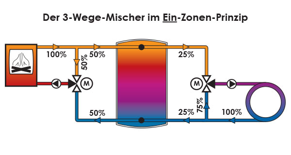
How much heat fits into your buffer tank depends on how well the system stores, or rather stratifies, the heat in the buffer. Most systems work like a spoon in a latte macchiato and inevitably destroy the stratification. Generated heat is fed into the upper buffer zone and taken out of it for heating. Return water from the consumers (radiators, underfloor heating,...), regardless of temperature, is fed back into the lower zone in an uncontrolled manner. This often leads to mixing of the desired temperature layers, so that only an average temperature is reached. Also, sooner or later it will not be possible to prevent destruction of the stratification due to downtimes.
Time in minutes / temperatures in °C
How does the two-zone principle work?
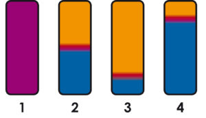
Charging states of buffer storage tanks
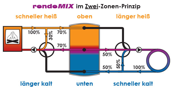
The loading assembly ensures that the upper zone of the buffer gets hot as quickly as possible and the lower zone stays cold for as long as possible by first removing the water from the middle. The unloading assembly takes only the heat from the buffer that is needed for the respective consumer, thus making the buffer in the lower zone cold faster and keeping the upper zone hot longer. The two-zone principle is the more efficient way to load or unload a buffer storage tank with heat. This is because only the best possible stratified storage tank can still absorb heat when it is already relatively full and release heat when it is already relatively empty. The secret of this benefit lies in the fact that with good stratification the storage tank is always hot at the top and always cold at the bottom (Fig., buffers 2-4), while the thoroughly mixed storage tank is warm from top to bottom (Fig., buffer 1). The border between hot and cold should be as abrupt as possible. The fuller the storage tank, the lower (picture, buffer 3), the emptier it is, the higher (picture, buffer 4) this limit is. In any case, a well stratified storage tank contains as little hot water as possible. Our rendeMix multi-way mixing manifolds ensure, via a central third connection on the storage tank, that priority is given to the hot water in order to create optimal stratification according to temperature level. In theory, a clear separation between hot and cold is created because, as can be seen in the illustration, the hot water is taken first, so that this is reduced to a small separation layer. This ensures that the buffer tank can be charged with the highest possible temperature down to the bottom when the draw-off by the consumers is smaller than what the boiler feeds in. 
Loading
The loading assembly (rMix 2×3 or rMix 3×3) for connecting heat generators to buffer storage tanks ensures that the upper zone of the storage tank gets hot as quickly as possible, as it first uses the warmer water from the centre of the storage tank. This means that the cold water in the bottom of the storage tank remains untouched for longer, making the use of renewable energies and flue gas heat exchangers more efficient. In the video you can see our rMix 2×3 which is used as a return flow booster. The mixer has the default, after the boiler circuit has heated up, to take first from the middle of the storage tank. If the temperature is too low, a certain amount of boiler water is added from the flow until then. If the boiler has heated up the storage tank sufficiently up to the middle connection, only then is cold water from the lower zone added.
Discharge
The discharge assembly (rMix 3×2 or rMix 3×4) for connecting heat consumers ensures that the upper zone of the storage tank remains hot for the longest possible time, as it first takes the still sufficiently hot water from the centre of the storage tank. In this way, the hot water in the upper part of the storage tank remains untouched for longer and the lower part of the storage tank gets cold much faster, which makes the use of renewable energies and flue gas heat exchangers more efficient.
Solution for 1 heating circuit
In the video you can see our rMix 3×2 which is used as a mixer for a mixed heating circuit. The mixer has the default of only taking water from the middle of the storage tank. If the temperature is too low, a certain amount of hot water from the upper zone is added. If it is too high, cold water from the lower zone is added. In the best case, the temperature in the centre of the storage tank is sufficient to feed the circuit without adding hot water from the upper zone. The lower the temperature spread between the storage tank flow and the heating circuit return, the less the flow has to be cooled with return water and the more return water reaches the storage tank, so that it gets cold faster in the lower zone.
Solution for 2 heating circuits
In the video you can see our rMix 3×4 which is used as a mixing manifold (with integrated return utilisation) for combining an unmixed heating circuit (H) with a mixed heating circuit (M) (also available as rMix 3×4+ for two mixed heating circuits). The mixer has the default of only taking from the middle of the storage tank. As the return of the first heating circuit (H) is connected to the middle connection (7), this can still be used as a supply for the second mixed heating circuit (M) if required before it is fed to the storage tank (return use). If the temperature is too low, a certain amount of hot water from the upper zone is added. If it is too high, cold water from the lower zone is added. In the best case, the temperature in the centre of the storage tank is sufficient to feed the circuit without adding hot water from the upper zone. The smaller the temperature spread between the storage tank flow and the heating circuit return, the less the flow has to be cooled down with return water and the more return water enters the storage tank, so that it gets cold faster in the lower zone. In this way, the entire amount of heat in circulation is utilised before further heat is extracted from the storage tank.
Are there any other advantages?
Tripled storage capacity
CHP plants (CHP, fuel cell...) and solar plants can run longer and pay for themselves faster!
Up to 100% more solar yield!
"If it remains cold in the bottom area of the buffer, the solar system can store more energy, up to twice the previous amount of heat over the year. That halves the payback time." (Dipl.-Ing. Fritz-Jürgen Hertweck, Friedrich Hertweck GmbH) "Down there in the buffer we never had around 20°C before." (Josef Bock, SHK Guild Schweinfurt)
Longer service life and fewer boiler starts
As with a car engine, frequent start-ups in a short period of time are the cause of high wear and tear and thus frequent repairs for a boiler. Two-zone operation with rendeMIX reduces these to a minimum.
Comfort gain
"We promise the log boiler operator a considerable gain in comfort. The reloading interval doubles. What used to be two days becomes four days." (Dipl.-Ing. Fritz-Jürgen Hertweck, Friedrich Hertweck GmbH) "The hot water is already there after 20 minutes!" (S. Ohnmacht, Haslenhof in Dauchingen)


