It is not only the storage volume that matters
 Investigation on existing heating system with buffer tank:
More buffer capacity with two-zone loading and unloading
The Institute for Building and Energy Systems at Biberach University of Applied Sciences, together with the manufacturer HG Baunach, investigated how the effective storage capacity can be optimised on an existing heating system with buffer storage. The subject of the study was a heating system in a six-family house owned by a SHK contractor. The effect of the loading and unloading behaviour on the usable heat quantity was investigated. The result is a significantly higher storage capacity after the buffer storage tank was converted to two-zone loading and unloading.
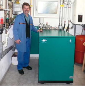
Figure 1: SHK entrepreneur Günther Muck in the boiler room of his rented six-family house. After the conversion to two-zone charging and discharging of the buffer tank, the CHP unit operates as a monovalent heat generator down to -10 °C outside temperature.
Buffer storage tanks have the task in heating systems of absorbing heat, storing it with as little loss as possible and releasing it to the consumers at the required temperature level. It makes sense to store the heat temporarily,
- when heat supply and heat demand occur at different times,
- to keep the switching cycles of heat generators such as CHP units, biomass boilers or heat pumps as low as possible,
- to make optimum use of the thermal energy produced from solar thermal plants or the operation of combined heat and power plants.
However, in the case of frequent switching on and off or insufficient use of solar heat, the cause is usually not the size of the buffer storage tank, but the amount of heat that can be used from it.
Buffer stored too little heat
This was also the assumption of the SHK entrepreneur Günther Muck when he attended a specialist lecture by the company HG Baunach on the hydraulic optimisation of heating systems at the SHK Guild in Schweinfurt. His rented apartment building in Dittelbrunn-Hambach, north of Schweinfurt, is heated by a mini CHP unit (Fig. 1). Six rented flats as well as storage rooms belonging to his SHK business are to be heated.
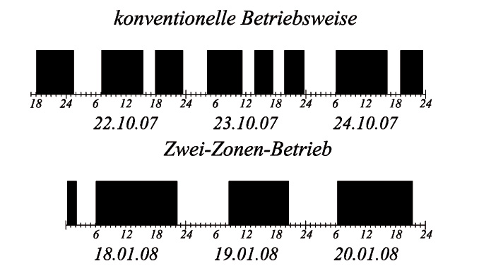
Figure 2: The short switching cycles of the heat generator before the conversion to two-zone charging and discharging (l.) indicate a low effective storage capacity of the buffer. After the conversion, there is only one CHP start per day (r.).
A buffer tank with a capacity of 1000 l is integrated as a hydraulic switch between the heat generators and the heat distribution. For the building constructed in 1996, Günther Muck had calculated a heating requirement (at that time still according to DIN 4701) of 18.1 kW. The Senertec CHP supplies 12.5 kWthA gas condensing boiler was also installed to cover the peak load. The heat consumers in the building are radiators with a design of 70/50 °C. As usual, the buffer integration was designed so that the flow is connected at the top and the return at the bottom. However, Günther Muck was not really satisfied with the operation of the system up to that point, because the CHP unit had up to five start-stop operations within 24 hours (Figure 2).
During the lecture event in Schweinfurt, he learnt in conversation with Hans-Georg Baunach that he was looking for existing systems that were suitable as test objects for the "rendeMIX" multi-port mixer. As part of a co-operation between HG Baunach and the Institute for Building and Energy Systems at Biberach University of Applied Sciences, Baunach then initiated an investigation into the buffer storage system. The aim was to achieve more efficient use of the storage volume and thus optimise the CHP running times.
Heating system as a test laboratory
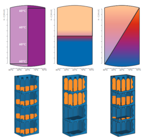
Figure 3: The graphs show the temperature distribution in an ideally mixed (l.), an ideally stratified (m.) and a linearly stratified storage tank (r.). In the theoretical view, real operation can be best described with the model of the linear stratified storage tank.
At Biberach University of Applied Sciences, Christian Dietrich, a prospective graduate engineer in building climatology, dealt with the topic of "Optimised integration of buffer storage tanks in hydraulic systems" as part of his thesis. An initial approach to investigating storage efficiency was to determine how many kWh of heat could ideally be stored in the 1000 litre buffer volume and how much of this could actually be used. Under ideal conditions, the storage volume at a CHP flow temperature of 90 °C and a return temperature from the heating circuit of 50 °C would result in a theoretical storage capacity of 47 kWh. However, the switching cycles of the CHP unit in Günther Muck's apartment block did not match these theoretical considerations (Fig. 3). This indicated that the effective storage capacity - the effectively available thermal energy in relation to the content of the buffer storage tank - must be significantly reduced. To determine this, the homeowner's heating system became a test laboratory for a few months: the existing three-way mixing valves were replaced by multi-way mixing manifolds. Temperature sensors and volume flow meters were placed on the storage tank and pipework.
The storage efficiency diagram brings the weakness to light
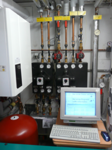
Fig. 4: The boiler room as a test laboratory: During the ongoing investigation of the system operation with two different buffer charging methods, the measured data were permanently recorded and transmitted to Biberach University of Applied Sciences via remote data transmission for evaluation.
For an initial test phase, the "rendeMIX" mixing distributors were initially set up so that the charging and discharging process corresponded to the previous circuit using three-way mixers. From mid-October 2007 to mid-February 2008, a PC set up in the boiler room recorded the measurement data in order to investigate the charging and discharging behaviour (Fig. 4a + 4b). According to Günther Muck's observations, almost all the typical weather conditions of a heating period prevailed during this time.
The measurement data was transmitted to Biberach University of Applied Sciences via remote data transmission and evaluated there by Christian Dietrich. The diploma student used the data to track down the actual storage efficiency. For this purpose, Dietrich developed a graphical representation called a storage efficiency diagram. In it, the height of the storage tank is plotted on the vertical Y-axis and the temperature horizontally on the X-axis. Several temperature sensors were positioned along the height of the buffer tank (Figure 5). From the coordinates of temperature and storage tank height, the storage capacity can be represented graphically as an area when entered in the storage efficiency diagram (Figure 6).
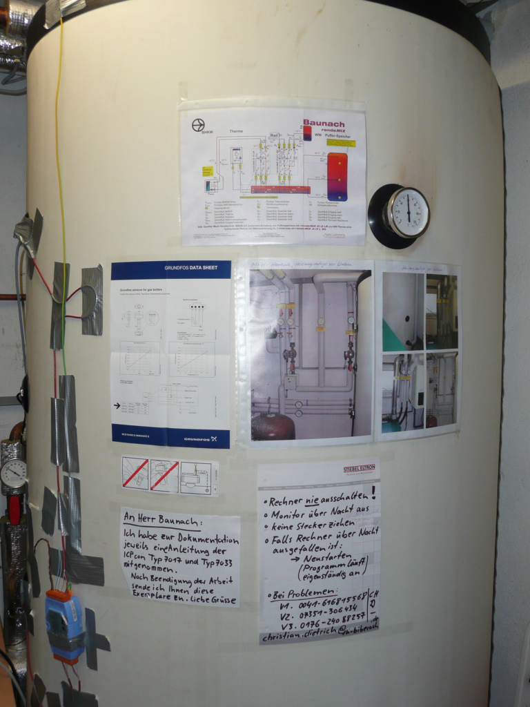
Figure 5: For the investigation of the storage efficiency, several temperature sensors were placed on the 1000-litre buffer storage tank, distributed over the height of the storage tank.
The result: The effective storage capacity was around 17 kWh with conventional discharge, which was 2.7 times less than the theoretically usable storage capacity of 47 kWh.
Get more heat out of the same buffer capacity
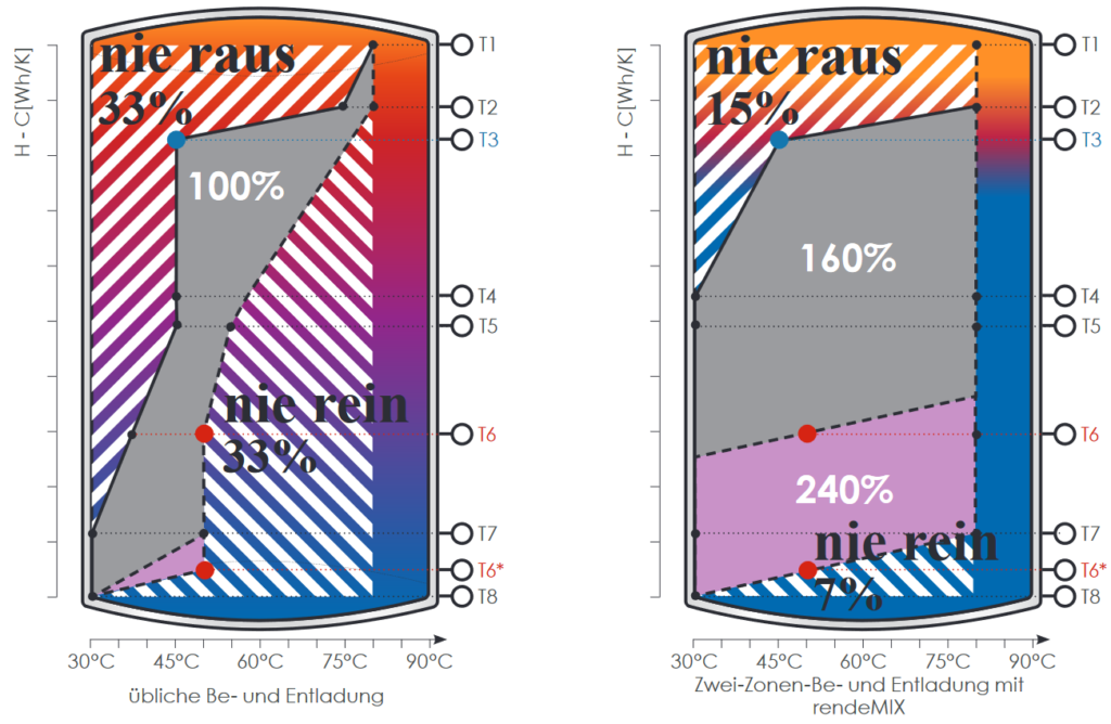
Figure 6: The before/after comparison shows the respective effective storage capacity of the buffer tank with conventional integration (l.) and after conversion to two-zone charging and discharging (r.).

Figure 7: The storage efficiency diagram specially developed by diploma student Christian Dietrich shows the amount of heat that can be effectively used in the buffer storage tank over the height of the storage tank.
The next step of the investigation was to consider which parameters influence the effectively usable storage capacity. The real loading and unloading, as shown in Figure 7 (storage graphic on the right), inevitably leads to mixing in the buffer storage, which significantly limits the effectively usable amount of heat. In the existing system, this type of buffer loading and unloading regularly destroyed the stratification. The mixing during loading and unloading therefore leads to the temperature being raised in the lower area of the storage tank, but falling in the upper area. It can be concluded from this that the efficiency of a hydraulic buffer depends significantly on the temperature distribution in the buffer storage. The storage efficiency is influenced by
- the flow temperature of the heat generator, which should be as high as possible,
- the return temperature of the consumer circuit, which should be as low as possible,
- and the flow conditions and velocities when entering the buffer tank.
Loading and unloading distributed over two zones
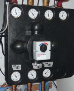
Figure 8: For the two-zone charging and discharging of the buffer tank, the existing three-way mixers were replaced by multi-way mixing manifolds of the type rendeMIX 3×4.
Instead of three-way mixers, a multi-way mixer is integrated in both the heat generator circuit and the consumer circuit. For the further part of the test, the charging strategy was changed to the "two-zone charging and discharging" operating mode. For this purpose, the already installed multi-way mixers were converted by replacing the actuators so that, depending on the setpoint specification, hot water is now mixed with warm water or warm water with cold water instead of hot water with cold water. This changes the loading and unloading behaviour of the buffer cylinder: when loading, the upper buffer zone (hot) is loaded first, which heats up more quickly as a result. The lower zone remains cold for longer. When discharging, heat is first removed from the lower buffer zone via the centre (!) cylinder connection, which cools down more quickly as a result. The upper buffer zone therefore remains at a high temperature level for longer.
The multi-way mixers (Fig. 8) are controlled via a three-point signal (230 V), just like the three-way mixers used previously. While the flow temperature of the heating circuit follows a weather-compensated heating curve during unloading, the return temperature to the heat generator is set to a fixed setpoint during loading. Two-zone charging thus also replaces an otherwise necessary return flow boost.
In the course of the investigation carried out, it also became clear that the positioning of the temperature sensors on the storage tank has a significant influence on the storage efficiency. The Senertec CHP unit in the system has two separate temperature sensors that are to be mounted at different heights on the buffer. When the setpoint on the upper sensor is undershot, the unit starts. If the temperature falls below the setpoint at the lower sensor, the machine switches off. As Christian Dietrich's evaluations showed, the two-zone charging and discharging increased the effective storage capacity by about 60 % from 17 kWh to 27.4 kWh. If, in addition, the lower sensor on the storage tank were moved even further down, the usable buffer efficiency could be increased by another approx. 30 to 50 % in the present case.
Two-zone principle applicable to any hydraulic system

Fig. 9 + 10: If the temperature in the middle of the storage tank is above the flow temperature of the consumer during the two-zone discharge of a buffer storage tank, the water is taken from the middle buffer connection and then mixed with the return water from the consumer to the desired temperature level. If the temperature at the middle storage connection drops below the flow temperature during discharge, the temperature is raised by mixing in warmer water from the upper storage area. The lower storage area can thus be discharged almost completely to return temperature.
SHK entrepreneur and homeowner Günther Muck noticed the effect of the increased storage capacity in the switching cycles of the mini CHP: Since the conversion to two-zone charging and discharging (Fig. 9), the unit only starts once a day, which is, however, due to a forced shutdown of the motor at 24-hour intervals. According to his observations, the CHP now works largely as a monovalent heat generator. The gas condensing boiler used for the peak load only switches on when the outside temperature reaches about -10 °C; in January 2009, this was only in operation for four days. The changeover of the buffer storage mode also had a positive effect on the energy status of the building: Günther Muck has since had an energy certificate drawn up for the six-family house, which certifies that the building has significantly improved energy efficiency.
However, the investigated heating system with CHP, gas condensing boiler and radiator heating circuit is only one example of the possible applications of the two-zone principle. For example, even lower return temperatures can be achieved in panel heating systems, as the lowest return temperature from the heat consumer circuit reaches the return of the heat generator and is not mixed with warmer return water on the way. The two-zone charging and discharging can also be transferred to any other hydraulic system that works with buffer storage, for example the integration of regenerative energies or refrigeration systems.
Our author Prof. Dr.-Ing. Alexander Floß became self-employed in 1995 with a TGA planning office, which is now dedicated to the areas of expert opinions, consulting and product development. Since 1999 he has been in charge of the areas of thermal energy systems and plant planning for the Building Climate Control and Energy Systems degree programme at Biberach University of Applied Sciences. Floß also heads the Institute for Building and Energy Systems there, telephone (0 73 51) 58 22 56, e-mail floss@hochschule-bc.de.
Our author Wolfgang Heinl runs an editorial office as a freelance trade journalist and PR manager specialising in the SHK sector and building services engineering, 88239 Wangen, Tel. (0 75 22) 90 94 31, e-mail wolfgang.heinl@t-online.de.


